Resources & Support
Select a product below to view support articles, videos, manuals, and obtain the latest updates.
How to translate a manual into another language
To translate a manual into another language, follow the steps below:
- Once the manual is open, select the contextual menu by selecting the “…” option in the upper-right hand corner of your screen.
- Select the translate option.
- Select your preferred language. Select translate.
Note: Due to limitations of Microsoft Translate, manuals greater than 50 pages in length currently do not support dynamic translation.
Specifications
| Image Size | 21.59 cm × 18 cm (8.5″ × 7.1″) |
| Scan Speed | ~30 seconds (depending on selected resolution) |
| Image Resolution | Up to 1200 DPI |
| Interface | USB Cable |
| Scan Head Dimensions | 35.9 cm long × 4.6cm diameter (14.125” x 1.8″) |
| Control Box Dimensions | 18 cm × 7.5 cm × 5 cm (7.125” × 3” × 2”) |
| Total Dimensions | 1950 g or 4.3 lbs |
* Scan speeds for handheld tablet included with scanner. Scan speeds vary with device used to operate scanner.
Root Tube Dimensions
| Inner Diameter | 5 cm (2″) |
| Outer Diameter | 5.7 cm (2.25″) |
| Wall Thickness | 3.2 mm (.125″) |
| Standard Length | 105 cm (41.3″) |
Get to know the CI-602 Narrow Gauge Root Imager
RootSnap! Webinar: From Root Imaging to Analysis - Best Practices and Applications
Rootsnap! Training Pt. 1: Setting Up Your Project and Importing Pictures with Rootsnap!
Rootsnap! Training Pt. 2: Tracing Out Root Systems and Accurately Adding Points in Rootsnap!
Rootsnap! Training Pt. 3: A Time Series Case Study and Data Export With Rootsnap!
Emerging Technologies for Phenotyping in Small Plot Agronomic Field Trials
Hidden Influence: Root system architecture and crop response to nutrition, irrigation, and climate
Reaching into the Rhizosphere - CID Minirhizotron Studies Impacting Commercial Peach and Citrus
CI-600 Webinar: Live Demonstration
CI-600 Non-Destructive Root Imager Demonstration for Plant Root Analysis
Back to Our Roots: Root research now and into the future [FULL WEBINAR]
Current Version
| Software | Download |
| Root Imager Offline Installer | RootImagerOfflineInstaller.exe |
| RootSnap! Software Version 1.4.0.113 | RootSnap v1.4.0.113.exe |
| RootSnap! Software Version 1.3.2.25 | CI690_Installer.exe |
| CI-602 Signed Driver Update 2023 | Driver Download |
| Driver Installation Instructions (Windows 11 or PC) | Driver Instructions Download |
-
What size auger bit should I use when installing root tubes?
-
For the CI-600 In-Situ Root Imager, we recommend a 3” (inch) diameter auger bit with two extension pieces for drilling holes to accommodate the 2.75” outer diameter of the CI-600 tubes.
For the CI-602 Narrow Gauge Root Imager, a 2.5″ auger bit with two extension pieces is recommended for the 2.25″ outer diameter of the 105 cm length CI-602 tubes.
When using the earthquake auger, brace the auger to steady the bit and to ensure that the angle of the holes for each tube placement is consistent. The hole created by the auger should be just larger than the tube to minimize the airspace around the tube exterior. With excess space, created by an unsteady auger bit, air pockets can occur between the tube and the soil, which will be visible in the root image and may lead to excess condensation on the exterior of the root tube. It is best to limit the space between tube exterior and soil wall to 8mm, or 0.3″.
-
Can I use my own 15-conductor cable?
-
You can source a longer 15-conductor cable if needed for your imager. Ensure that all 15 pins are physically wired inside the cable. An easily identifiable symptom of a wrong cable is that the scan head will light up with a blue light. We recommend the following cable for a longer 15-conductor cable:
http://www.cablestogo.com/product/50213/10ft-select-vga-video-cable-m-m-in-wall-cmg-rated
Under the product features of the cable linked, they list that all 15 pins are wired to support DDC2 (E-DDC) and EDID.
-
What type of image quality is to be expected with my root imager?
-
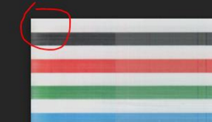
Image quality can sometimes be improved through calibration. View the images below for examples of typical quality verses necessary calibration.
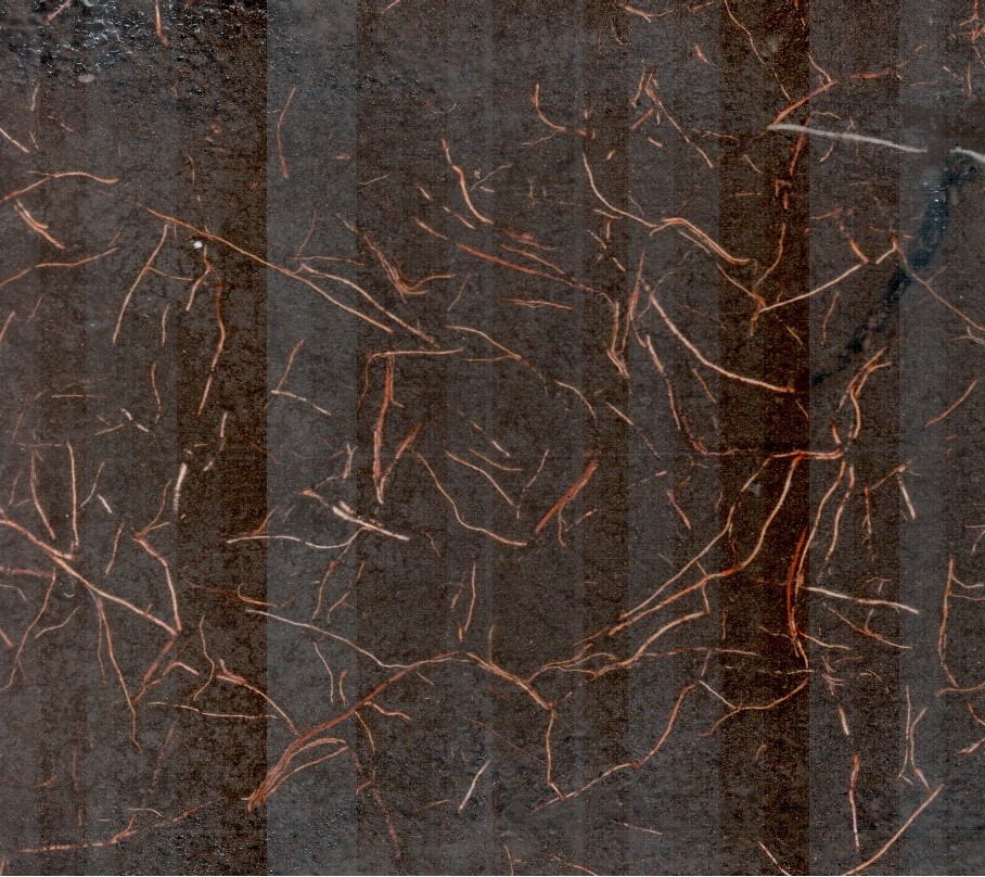
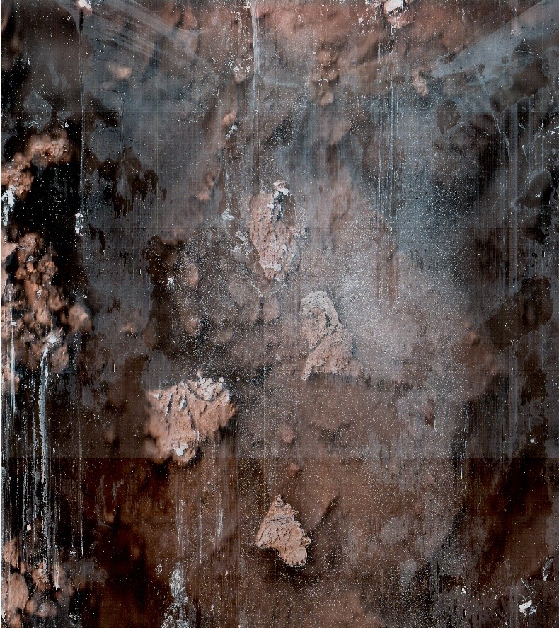
No Recalibration Necessary

Bands of lighter or darker pixels, visible as wide stripes across the image
These are typical of images captured with the CI-600 and CI-602. The scan head is composed of banks of sensors for which the calibration may be slightly different, resulting in thick bands of slightly lighter or darker hue.
Uneven, colorless, thin lines on image
These are a result of the fibers that make up the root tubes. The imager is essentially capturing the walls of the root tube and then the soil and roots beyond. These thin lines should not be consistent from tube-to-tube if it is truly the root tube fibers. This is caused by the soil not being packed tightly around the outside of the tube.
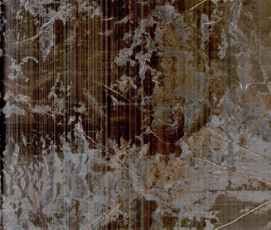
Recalibration Necessary
Thin, consistently pattered stripes
These kinds of images are a result of either a failed calibration, improper connection between instrument and PC, or failed hardware. To troubleshoot, ensure you are using the proper cables and that your connections are secure. Next, try a recalibration using the provided calibration tube. If recalibration does not improve your images, contact support@cid-inc.com.
-
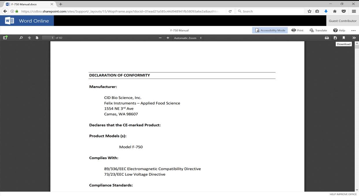
How do I download the manual as a pdf document from the website?
-
- Open up the desired manual in a browser window
- Click ‘Accessibility Mode’
- Select the download icon. The manual will download as a pdf.
-
Calibration doesn’t seem to be improving my images, what should I do?
-
- Ensure you are using the most current software version on your PC. Please see our CI-602 software page for the most current release.
- Proper positioning of the imager in the calibration tube is the most important aspect of a calibration. While there is an indicator of the proper insertion position on the calibration tube, it can be necessary to manually adjust the positioning. See the steps below.
- Insert the imager at the position noted on the calibration tube with white dots properly aligned as well.
- Take a test scan at 100 dpi.
- The image should clearly show a white band at the very top, followed by a black band. See the image below as an example.
- Insert the imager slightly clockwise from the indicated home position if you do not see the white stripe on top of the black stripe. Insert the imager slightly counterclockwise from the indicated home position if there is anything above the white stripe in the image.
- Take another test scan and repeat as necessary.
- Change the number of calibration scans run for each dpi. Navigate to advanced>calibrate>options># of samples and set this to 48.
-
How do I install root tubes for use with my imager?
-
The goal is to dig a hole deep enough to fit a root tube angled at about 450 without any clear unpainted plastic showing above ground once the tube is buried. The top opening of the tube will be ideally facing to the NE; you can change orientation if there’s an obstruction or slope.
Before heading to the field, look inside the tubes. Remove any “fuzzies” on the inside of the tubes left over from cutting the tube. You can blow them out with compressed air or gently push a soft very slightly moistened cloth through the tube. All the tubes should have plastic caps installed on both the top and bottom before taking out to the field.
- Clear the area where you’re going to dig your hole. It should be free of woody plants. Plan ahead to ensure sufficient space to repeatedly insert and remove scanner.
- Lay down the tarp next to your future hole and dig a shallow trench that’s approximately 15-20 cm by 65-70 cm using a Pulaski. Throw the top layer of soil on the tarp near the side where the tube will be sticking out of the ground.
- Start digging using the sharp shooter shovel. Try to dig your hole at a 45 0 As you’re digging, throw the soil onto the tarp in the order of most shallow to deepest.
- Once the deep end is at a depth of at least 65cm and it looks like the angle is about right, put your tube in to test it out. NO need to remove the paper from the tube quite yet. Note: it can be helpful to use a spare tube in the initial stages of installation.
- Use the level or your compass to check the angle of the tube. Adjust accordingly and determine if there will be any clear plastic sticking out above the ground. This means the bottom portion of the paint on top of the tube should be below ground level.
- If you have a good angle but some clear plastic is still peeking above ground level, go deeper!
- Deep enough now? It’s sifting time! Gently peel the tape of the end of the tube, and try not to remove any paint as you take off the tape. Remove the paper and wipe any “fuzzies” off of the tube. Very gently lay your tube into the hole.
- Start at the deep end and use the deepest soil from the tarp first. Throw a few handfuls in a sifter and sift away.
Return the chunks of soil to your tarp-you will need these to fill in the hole later. Pack the soil under the tube. Put one of your hands on top of the tube while you’re packing the soil – otherwise the angle will get steeper as you fill in. There should be no gaps in the soil or excessive debris touching the outside of the tube. You can shine a light over the tube to get a better view, and use a bent-over pin flag to pack in hard-to-reach nooks and crannies. Note: you can lower a flashlight on a string into the tube, but beware of scratching the inside of the tube in the process!
- Continue sifting and packing the soil underneath the tube. If everything looks well-packed with no gaps or debris, begin sifting the soil onto the top of the tube as well.
- When you’ve gotten to the top and assured the soil is well-packed without gaps or excessive debris, dump the remaining soil on the tarp into the hole. Smooth it over. It is alright to harvest soil from elsewhere if that soil is not enough to fill in the hole and leave a smooth soil surface.
Il) If it’s filled in and it all looks good, you’re done! The process typically takes 1-1.5 hours, but can vary.
Equipment:
Small hand towel
Tarp or heavy-duty garbage bag
Sharp shooter shovel
Sifter
Flashlight
Hand trowel
Pin flag bent over
Root tube
Soil knife
Level set to 45 0 or compass, or appropriate
Meter stick
app on smart phone
Pulaski
Additional documentation on root tube installation can be found here.
-
Do I have to purchase RootSnap! separately?
-
No! RootSnap! software is free to all users of CID Bio-Science Root Imagers.
-
Does this product come with a warranty?
-
All CID instruments come with a 12-month warranty from the point of sale. The warranty covers repairing and replacing defective parts of the instrument that were manufactured directly by CID Bio-Science. The warranty does not cover wear and tear, neglect, misuse, accident, or excessive deterioration. Further, repair and alteration by an unauthorized party voids the warranty. More information can be found in the operation manual of your instrument.
-
Is the CI-600 waterproof?
-
The CI-602 is not designed to be waterproof and should not be used underwater. The CI-602 is designed to be water-resistant. Use in light rain is fine, however, there are electronics that can be damaged from water entering the instrument, so it is not recommended to use the CI-602 during heavy rainfall. Furthermore, it should be noted that the tablet provided with the CI-602 is not waterproof and a waterproof case would need to be purchased for use in wet conditions.
-
What are the minimum and maximum operating temperatures?
-
You can use the CI-602 root imager in temperatures ranging from -5° C to 55° C.
-
What different types of researchers use the Narrow Gauge Root Imager?
-
Crop, forestry, environmental, plant, climate, hydrology, and soil researchers all benefit enormously from the metrics that the Narrow Gauge Root Imager provides.